|
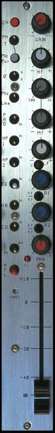
CS 208 INPUT MODULE |
|||
|
|
Left Section | ||
|
1. CH : |
Channel
Power (down = on) Do not switch during recording. |
||
| 2. PH / T : | Phantom
Power, �T� power (AB). (phantom power is normally 48v, see
layout A to change to 12v). |
||
| 3. Mic Pwr : | Turns
on mic power (down = on). Mic power type selected by the switch above. |
||
| 4. � : | N
= normal, R = reverse. Audio phase only. |
||
| 5. Mic/Line : | Microphone
or line level in. |
||
| 6. Pad : | Attenuator
to reduce either mic or line input levels. |
||
| 7. HP1 : | High
pass filter, pre-transformer. |
||
| 8. HP2 : | High
pass filter, post transformer & preAmps. |
||
| 9. EQ : | Equalizer
bypass. Affects HF, MF & LF filters, not HP filters. |
||
| 10. AB : | Assigns
channel to AB mix busses Further selection is made by the pan pot. A = L, B = R. |
||
| 11. CD : | Assigns
channel to CD mix busses. Further selection is made by the pan pot. C = L, D = R. |
||
| 12. Lim : | The
limiter is a symmetrical peak detecting type & is completely out of
circut when switched off. Threshold: See (14). Attack &
release times are preset internally (see layout A to change). |
||
| 13. PFL : | Pre-fade
listen. Sends selected channel to phones 1 only. (Cuts out
all other inputs to phones). Can be changed to AFL (see layout A). |
||
| 14. Thres : | Limiter
threshold. Clockwise = lower threshold. |
||
| 15. O / L : | Near
overload or limiter threshold indicator (see layout A). |
||
| Right Section | |||
| 16. Gain : | Mic
/ Line preAmp gain. |
||
| 17. HF : | High
frequency amplitude control. |
||
| 18. MF 500, 5k : | Mid-frequency
select. |
||
| 19. MF : | Mid-frequency
amplitude control. |
||
| 20. LF : | Low
frequency amplitude control. |
||
|
21. S : |
Invert
phase option to B & D busses. 1 pair of channels could be used to
decode a M / S microphone configuration. |
||
| 22. A1 : | Aux
1 send (the aux sends are not affected by the AB, CD mix bus switches). |
||
| 23. PF / AF : | Selects
pre or after fader for Aux 1 send. |
||
| 24. A2 : | Aux
2 send. |
||
| 25. PF / AF : | Selects
pre or after fader for Aux 2 send. |
||
| 26. Pan : | L
= A and/or C, R = B and/or D. Example: A out only. AB switch in, CD switch out, Pan L (left). |
||
| 27. Channel fader | |||
|
See specifications & application notes for further details. |
|||
|
© Cooper Sound Systems, Inc. |
|||